- Field-Cycling Add-on Coils
-
In a project funded by an EPSRC Follow-on Fund grant, we investigated the feasibility of add-on hardware to allow FFC-MRI to be performed on some existing commercial MRI scanners. The type of technology we investigated could allow field-cycling on vertical-field, open-geometry magnets, by the use of a "pancake" field-offset insert coil. The figure below illustrates this concept.

Sketch of a "pancake" field-offset coil inside a vertical-field, open-geometry MRI system Together with project partners Tesla Engineering Ltd. we produced a prototype field-offset magnet coil and successfully tested it in our 59 mT vertical-field MRI system. Although this is not an open-geometry MRI system, it nevertheless served as an excellent test-bed for the offset-coil add-on concept.

Prototype "pancake" field-offset coil, ready for insertion into bore of 59 mT vertical-field MRI system. Water cooling pipes and electrical connections can be seen.
Solenoidal RF coil in cylindrical shield sitting on top of offset coil is for test purposes only - Localised Relaxometry
-
We have investigated methods to generate T1 dispersion plots from precisely-defined local volumes within larger samples. This could be used, for example, to generate a T1 dispersion graph of tumour tissue, even if the tumour was deep inside an organ of the body. In this way, the T1 dispersion data would pertain only to the tumour, and would not be "contaminated" by the T1 dispersion of surrounding normal tissue.
In order for this to work, we had to develop (a) a method of selecting the desired volume for T1 dispersion measurement on pilot MR images of the sample (or patient) under study; (b) a reliable method of limiting the NMR signals to the image-selected volume of the sample (or patient); and (c) methods of analysing and displaying the T1 dispersion plots.
Localisation of the NMR signals (and hence the T1 dispersion data) in three dimensions was accomplished using a technique borrowed from NMR spectroscopy, called "PRESS". It involves applying selective 90° and 180° radiofrequency pulses in the presence of orthogonal magnetic field gradients. For T1 measurement the PRESS module is incorporated into an inversion-recovery pulse sequence, using an adiabatic fast passage (AFP) pulse for improved inversion efficiency. The pulse sequence is applied in an interleaved manner (AFP-on, AFP-off) to allow T1 calculation by a 2-point method.

Field-cycling inversion-recovery pulse sequence using PRESS localisation. Spins are inverted using the AFP pulse, then relaxation occurs at field B0E, followed by selective excitation and echo formation. The sequence is repeated at a range of B0E values to build up a T1 dispersion curve. In order to measure a localised T1 dispersion curve, one or more pilot images are collected, on which regions-of-interest are drawn using the mouse. These define the cuboid volume from which the NMR signals are produced. The scanner's software then calculates the necessary magnetic field gradient values (G1, G2 and G3 in the above diagram), then runs the pulse sequence to generate the data. An example of a pilot image and a resulting R1 dispersion plot (R1 = 1/T1) are shown below.
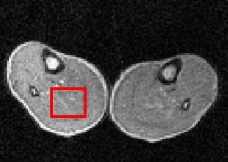
Pilot image (59 mT) through thighs of a volunteer, showing in red the region-of-interest where it intersects the image plane. 
R1 dispersion curve on the right was obtained from the selected volume. The quadrupole peaks due to immobile protein within muscle can clearly be seen. - Rapid FFC-MRI
-
In its basic implementation, FFC-MRI is a relatively slow process. This is because (as with conventional MRI) the pulse sequence must be repeated N times in order to fill up k-space for an N x N pixel image. Furthermore, each line of the pulse sequence includes a field-cycling "event" - i.e. a ramp to the Evolution magnetic field, followed by a period there of ca. 0.5 seconds, followed by a ramp to the Detection field. FFC-MRI is slowed down still further when it is performed over a range of different evolution fields, in order to achieve relaxometric imaging. This project aimed to investigate how existing rapid MR imaging techniques could be adapted to FFC-MRI to offset this increase in scan time.
One solution was to develop a field-cycling version of the well known "Fast Spin-Echo" sequence. This sequence works by using multiple 180° radiofrequency refocusing pulses to generate a "train" of NMR echoes. By separately encoding each echo in the train an increase in image acquisition speed equal to the number of refocusing pulses can be achieved. To perform field cycling experiments, the spins are inverted using an adiabatic inversion pulse and allowed to evolve at the Evolution magnetic field before the imaging sequence is performed at the Detection field.
By collecting inversion-recovery images over a range of evolution magnetic fields and using a 2-point method it is possible to determine T1 at each value of the evolution field. Using centric ordered phase encoding this sequence allows a trade-off in image resolution vs scan time while ensuring that measured T1 accuracy is independent of the speed-up factor.

The Field-Cycled Fast Spin-Echo sequence. A slice of spins is first inverted using a hyperbolic secant AFP pulse. Then the field is switched to the evolution field (B0E) at which the spins relax. The magnetic field then returns to the detection field and image data is collected using the fast spin-echo technique. The speed-up factor n is equal to the number of lines of k-space collected following each field-cycling ramp. Experiments were carried out to determine the effect of increasing the speed-up factor on image quality. The images below were obtained on our 59 mT whole-body FFC-MRI scanner.
Comparison of 4 different speed up factors. Image blurring due to spin-spin relaxation only becomes apparent at higher speed up factors.

Image A) spin echo image with no speed up factor, acquisition time 128 s.
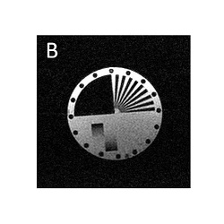
Image B) Speed up factor 2. Acquisition time 65 s.
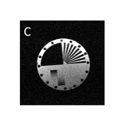
Image C) Speed up factor 4, acquisition time 34s.

Image D) Speed up factor 8, acquisition time 17s. Relaxometric imaging was implemented using Fast Spin Echo FFC-MRI; results are shown below.
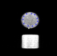
Set of FSE FFC-MRI images, obtained using a speed-up factor of 4 (i.e. 4 echoes in each echo train), using 3 averages. Images were obtained at 35 different evolution field strengths. The total scan time was 31 minutes. The phantom included a circular bottle containing gelled bovine serum albumin (BSA) protein. 
R1 (1/T1) dispersion plot derived from the set of images, from a region of interest drawn around the BSA sample. The quadrupole peaks, arising due to immobile protein in the sample, are clearly visible, demonstrating that relaxometry can be performed using this sequence with acceptable scan times. - Biomedical Applications
-
This page summarises some of our recent bio-medical applications of FFC. Further details can be found in the downloadable abstracts and manuscripts on our Publications page.
Thrombosis monitored by FFC relaxometry
Blood clot formation (thrombosis) involves the controlled polymerisation and cross-linking of fibrinogen to form a network of fibrin fibres which form the rigid skeleton of the clot. Fibrinogen protein is dissolved in blood plasma; due to its mobility in solution, it does not give rise to quadrupolar peaks in its R1 dispersion plot. However, the polymerisation of fibrinogen and its cross-linking to form a fibrin network leads to immobilisation of the protein, and the associated observation of quadrupole peaks.
In this study model thrombi were produced in the laboratory, using a range of starting concentrations of fibrinogen in solution. Clot formation was initiated by the addition of thrombin enzyme, after which FFC relaxometry was carried out on the 1-mL (approximately) samples, using our bench-top FFC-NMR relaxometer. The figure below shows an R1 dispersion plot of fibrinogen solution at 10 mg/mL concentration (open circles), together with a dispersion plot obtained after clot formation (closed circles).
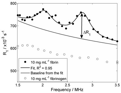
R1 dispersion plots of fibrinogen in solution (open circles) and fibrin clot (closed circles). Quadrupole peaks are absent prior to clotting, but evident afterwards due to immobilisation of the protein The experiment was repeated using a range of starting concentrations of fibrinogen, in order to see if the 'height' of the quadrupole peaks (ΔR1 in the figure above) was proportional to the immobile protein concentration. The figure below shows the result of these experiments:

Effect of fibrinogen concentration on the 'height' of the quadrupole peaks ΔR1. The expected linear relationship is observed. This study showed that FFC-NMR relaxometry can monitor clot formation in a model of thrombosis. Work is progressing to investigate more complex thrombosis models. We plan to extend this work, in the hope that FFC-MRI can provide extra information on blood clots in patients.
Detection of osteoarthritis in knee and hip joints by FFC NMR
Osteoarthritis is a debilitating disease of the joints. There is a great need for a diagnostic method that can detect osteoarthritic changes in joint tissues early in the progress of the disease, when drug treatment may be possible. However, at present no such technique is sufficiently reliable.
It is known that the concentration of proteins called glycans decreases in osteoarthritis. We are investigating whether FFC NMR relaxometry can detect differences in the measured quadrupole peaks, between normal and diseased joints, since the quadrupole peaks are strongly dependent on a tissue's immobile protein content. If so, FFC-MRI may be a viable method of detecting disease.
Ethical approval for the study was granted by the North of Scotland Research Ethics Committee. Samples of cartilage were obtained from patients with osteoarthritis during hip or knee surgery. Samples of normal cartilage were obtained from patients undergoing hip replacement for osteoporotic fractured neck of femur with no preceding osteoarthritis of the hip.
Relaxometry measurements of cartilage were carried out using our bench-top FFC NMR relaxometer. The figure below shows a comparison of R1 dispersion curves obtained from cartilage samples from normal and osteoarthritic patients - there is clearly a difference between the two.
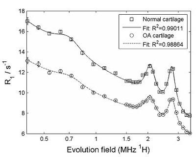
FFC-NMR relaxometry on normal cartilage (squares) and cartilage from patient with osteoarthritis (circles). The difference between the two is clear. The data were further analysed by subtracting the "background" from the curves, in order to isolate the quadrupole peaks, as shown below.
The amplitude of the quadrupolar peaks is clearly reduced in the osteoarthritic cartilage.
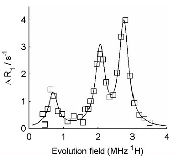
Isolated (background-subtracted) quadrupole peaks obtained using FFC-NMR relaxometry on normal cartilage 
Isolated (background-subtracted) quadrupole peaks obtained using FFC-NMR relaxometry on cartilage from an osteoarthritic joint These preliminary results indicate that there appears to be significant potential for the detection of osteoarthritic changes in joints using FFC methods. Further research is being carried out in our labs, funded by a grant from Arthritis Research UK .
- PEDRI free radical imaging
-
Field-cycling is used in a technique that we developed in Aberdeen called FC-PEDRI, with the aim of imaging the distribution of free radicals in biological samples and tissues. Indeed, our involvement with Field-Cycling magnetic resonance dates back to 1989, when we started to use it in this context.
Free Radical Imaging
Free radicals are defined as molecules with one or more unpaired electron in their outer orbital. Because of this property, they tend to be quite reactive. Free radicals are involved in normal metabolism, and are always present in the human body, but normally at very low concentrations. There is considerable interest in free radicals among the medical research community, because changes in their concentrations are believed to be involved in the early stages of many diseases, including cancer, inflammatory disease, heart disease and many more. Our aim is to design, build and use "scanners" to show where these free radicals are within the body, and to view the response of these free radicals to various forms of treatment.
PEDRI
PEDRI (Proton-Electron Double-Resonance Imaging) is a technique for imaging the distribution of free radicals within the body. PEDRI is able to detect low concentrations of free radicals and can also produce very high quality images, showing the distribution of free radicals in large samples. PEDRI makes use of a double resonance magnetic resonance technique called the Overhauser Effect.
The Overhauser Effect is essentially a combination of nuclear magnetic resonance (NMR) and electron spin resonance (ESR). The NMR signal is obtained in the usual way, by applying pulses of radiowaves at the NMR frequency. At the same time, the free radical's unpaired electrons are irradiated by applying an irradiation (radiowave or microwave) at the ESR frequency. If there is good magnetic coupling between the unpaired electrons and the water hydrogen nuclei, the ESR irradiation can cause a transfer of polarisation from the electrons to the nuclear spins, resulting in an amplification or "enhancement" of the measured NMR signal. In theory, the enhancement can be up to 330-fold, though in practice enhancement factors of 10- to 50-fold are more commonly observed.
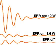
NMR FIDs from solution of TEMPOL free radical, at different EPR irradiation powers PEDRI is the imaging version of the Overhauser experiment. The ESR resonance of the free radicals of interest is irradiated during the collection of an MR image. The Overhauser effect causes an enhancement of the NMR signal in parts of the sample containing the free radical, and these regions "light up" in the resulting image, showing the distribution of the free radical.
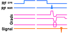
PEDRI pulse sequence 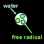
diagram of free radical phantom (diameter 2 cm) 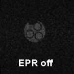
0.02 tesla EPR-off image of phantom 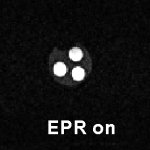
0.02 tesla EPR-on image, showing Overhauser enhancement in regions containing free radical. PEDRI imagers normally use low-field magnets with magnetic fields of about 0.01 tesla (as opposed to the 1 tesla or so used in clinical MRI systems). This is because the ESR frequency is 659 times the NMR frequency in a given magnetic field. So, in a 1 tesla magnet, the ESR frequency would be 28 GHz, well into the microwave part of the electromagnetic spectrum, which would cook any biological sample being imaged! Reducing the magnetic field to 0.01 tesla brings the ESR frequency to a more manageable 280 MHz.
Field-Cycled PEDRI (FC-PEDRI)
The down side of using a low magnetic field is that the image quality suffers (high fields are used in clinical MRI to improve the images). The ideal would be to irradiate the ESR at low field - hence low frequency and no cooking (!) - and to detect the NMR signals at high field - to give good image quality. This is what we do in Field-Cycled PEDRI. In the field-cycled PEDRI (FC-PEDRI) experiment the magnetic field is switched between two levels. The magnetic field starts at a low value (called the "evolution" field, typically 0.004 tesla), and the ESR irradiation is applied at about 120 MHz. Then the field is switched to a high value (called the "detection" field, 0.06 tesla in our prototype system), at which the imaging gradients are applied and the NMR signals detected.
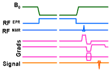
FC-PEDRI pulse sequence An advantage of PEDRI over "direct" ESR-based free radical imaging techniques is that the image formation is entirely by NMR, as opposed to ESR. This means that the spatial resolution is independent of the ESR linewidth of the free radical under study. Another related advantage is that PEDRI can make use of standard MRI pulse sequences, including rapid imaging techniques.
In our whole-body system, the detection magnetic field is provided by a whole-body sized permanent magnet which generates a vertical field of 59 mT. Just inside the bore of the permanent magnet is a resistive magnet, made from copper conductor in a saddle configuration. When electric current is sent through the resistive magnet windings they generate a field of up to 59 mT, in opposition to the permanent magnet's field. In this way, switching on and off the current switches the total field in the centre of the magnet down and up in value, and the precise field value can be selected by choosing the correct current to send through the resistive magnet coils.

Whole-body FC-MRI scanner, which is also used for FC-PEDRI In addition to the usual transmit/receive radiofrequency (RF) coil needed in MRI, FC-PEDRI also requires hardware to generate and apply the RF for ESR irradiation. The NMR transmit/receive coil and the ESR coil/resonator are usually combined into a double-resonance coil assembly. Because the NMR and ESR frequencies are usually far apart (even when field cycling is used), separate resonant structures are usually used. The figure below shows a double-resonant coil assembly, comprising a solenoidal NMR coil (2.5 MHz) and a birdcage resonator for ESR irradiation (51 MHz).

FC-PEDRI RF coil assembly, comprising split-solenoid NMR transmit/receive coil, and birdcage resonator for ESR irradiation.
Assembly is mounted inside a cylindrical RF shield made of copper foil on a Perspex former. - IDentIFY - EU H2020 Project
-
IDentIFY - "Improving Diagnosis by Fast Field-Cycling MRI" - is a €6.6M research project funded through the EU Horizon 2020 Programme.
The project ran from 1st January 2016 to 31st December 2019; it involved partners from 9 sites across Europe (7 academic sites and 2 SMEs), led by The University of Aberdeen.
